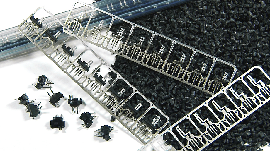
Connector assembly for connecting piezo sensors to a printed board made of PBT/GF30
Capacity
- Length of cycle:
- 1 sec. per moulded part
- Injection moulding tool format:
8-fold- Annual production:
- 18 million
(3-shift operation, 250 working days p.a., 85% availability)
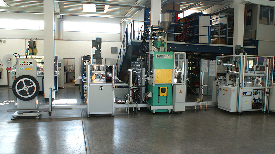
Brief description:
A flat pre-punched strip is drawn from a reel and fed into a bending station. A pneumatic gripper feed pushes the punched strip into a bending tool, where one contact pair per cycle is given a Z-shaped contour. The cycle length of this bending process is 1 second. Directly downstream of the bending tool an image recognition system checks the result of the bending. The punched strip with the contacts bent in a Z-shape then runs through a loop control before it gets pulled into an injection-moulding tool. This 8-fold injection-moulding tool is installed on a vertical injection-moulding machine. The punched strip is pulled over the cavities by another gripper feed. After it has been fed forward, a downward movement centres the punched strip within the cavities. The gating is done using a 3-plate gate. After the tool opens, this gets stripped by the die plate on the jet side and taken out of the tool by an actuator-powered extractor. A hot-embossing station additionally integrated within the injection-moulding station marks start-up / bad parts from the injection-moulding process with a punch mark on the insert mould. This mark is recognised later in the process by an image recognition system, so that these bad parts get automatically deselected. After the injection moulding, the insert-moulded punched strip moves into a separating station. Inside a 4-fold tool the plug contacts get separated from the carrier strip and pressed into a movable cutting plate.
After the separation process, this cutting plate is pushed out by a pneumatic cylinder so that a transfer handling device can remove the separated plug contacts and transfer them into a rotary indexing table’s workpiece holders. Several electrical and optical end-item inspection devices are now built onto this rotary indexing table in order to perform the electrical run-through and an insulation test of the insert-moulded contact pairs.
Image recognition systems then make sure that there are no injection-moulding errors and no malpositioning of the free contact ends.
After this end-item inspection has been run, good parts are also marked by hot embossing before an unload handling device deposits the good parts in a provisional storage area. From this temporary position the finished parts are pushed into plastic tubes. When the tubes are completely full, a labelling system sticks a written label on them. Prior to it being stuck on, the product-specific data gets printed onto the label. These packaging tubes are fed to and from this position via an appropriately paced conveyor belt with a specially made profile for holding these tubes in the right position.